Course Description

Art B2050, Fall 2013, DIAP at CCNY
A survey of modern electromechanical construction. Lessons interweave hardware, firmware, software and networking. Specific focus on paper and cardboard prototyping.

Wednesday, October 30, 2013

Week 9, 10/30: Sensors

Sensors come in many shapes and sizes. Understanding what types of sensors are around at what price points will help you shape your projects. The thing most of you were interested in sensing was the presence and proximity of people, so here are two sensors for that purpose. A piezo sensor detects vibration— a very crude version of a microphone. A ping sensor emits and detects an ultrasonic pulse; the time it takes the pulse to return to the sensor tells you how far away the closest object is. 

Sensors typically have two or three terminals. Every sensors needs power, ground, and at least one signal wire. With two-terminal sensors, like photoresistors and piezos, a voltage divider is required. The ground terminal connects to ground; the positive terminal connects to the signal input pin and also to a resistor; the resistor connects to the source voltage.


Piezo Code
int ledPin = 13;
int knockSensor = 0; 
byte val = 0;
int statePin = LOW;
int THRESHOLD = 100;

void setup(){
  pinMode(ledPin, OUTPUT); 
  Serial.begin(9600);
}

void loop(){
  val = analogRead(knockSensor); 
  if (val >= THRESHOLD) {
    statePin = !statePin;
    digitalWrite(ledPin, statePin);
    Serial.println("Knock!");
  }
  delay(100);
}

Ping Code
const int pingPin = 10;

void setup() {
  Serial.begin(9600);
}

void loop(){
  Serial.println(ping());
  delay(100);
}

int ping(){
  long duration, cm;
  pinMode(pingPin, OUTPUT);
  digitalWrite(pingPin, LOW);
  delayMicroseconds(2);
  digitalWrite(pingPin, HIGH);
  delayMicroseconds(5);
  digitalWrite(pingPin, LOW);
  pinMode(pingPin, INPUT);
  duration = pulseIn(pingPin, HIGH);
  cm = microsecondsToCentimeters(duration);
  Serial.print(cm);
  Serial.print("cm");
  Serial.println();
  return cm;
}

long microsecondsToCentimeters(long microseconds){
  return microseconds / 29 / 2;
}


Wednesday, October 16, 2013

Week 8, 10/23: Processing

Today we'll look at the art history of mechanical systems. Here's a link to the image gallery, here's a link to the reading, here's a link to the circuit symbol index. We'll also talk about how the four programming paradigms— imperative, functional, object-oriented, logic— and how they're all encapsulated in the familiar line, Serial.println("hello world");

The goal of today's workshop is to get Arduino communicating with Processing. It's easier to go from Processing to Arduino than the reverse, so we'll start there. The one trick to getting this working is to select the correct Serial port in Processing. When you first launch the Processing code, it will list the Serial ports in the debugging window. One will match the board ID# you selected in the Arduino/Tools menu. Whatever number in the list matches your board ID# will be substituted for 0 in the line port = new Serial(this, Serial.list()[0], 9600);


Arduino Code
const int ledPin = 13; 
int incomingByte;

void setup(){
  Serial.begin(9600);
  pinMode(ledPin, OUTPUT);
}

void loop() {
  if(Serial.available() > 0){
    incomingByte = Serial.read();
    if(incomingByte == 'H'){
      digitalWrite(ledPin, HIGH);
    } 
    if(incomingByte == 'L'){
      digitalWrite(ledPin, LOW);
    }
  }
}

Processing Code
import processing.serial.*; 
float boxX;
float boxY;
int boxSize = 20;
boolean mouseOverBox = false;
Serial port; 

void setup(){
  size(200, 200);
  boxX = width/2.0;
  boxY = height/2.0;
  rectMode(RADIUS); 
  println(Serial.list());  // find your Arduino in log list
  port = new Serial(this, Serial.list()[0], 9600);
}

void draw(){ 
  background(0);
  if (mouseX > boxX-boxSize && mouseX < boxX+boxSize && 
    mouseY > boxY-boxSize && mouseY < boxY+boxSize) {
    mouseOverBox = true;  
    stroke(255); 
    fill(153);
    port.write('H');
  } 
  else {
    stroke(153);
    fill(153);
    port.write('L');      
    mouseOverBox = false;
  }

  rect(boxX, boxY, boxSize, boxSize);
}

Week 7, 10/16: Arduino


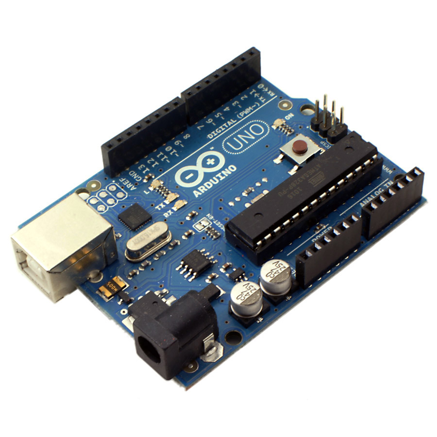
Arduino is a development platform consisting of a microcontroller and a programming environment. There have been several versions of Arduino; the model we're using is called the Uno. It has 13 Digital I/O pins and 6 Analog I/O pins. This is a typical Arduino workflow:
  1. Select desired components
  2. Google "[name of component] + Arduino" to find examples of wiring and code
  3. Wire and code one component at a time
  4. Splice the code together
The Arduino microcontroller can be purchased here, and the Arduino environment can be downloaded here. Sparkfun is a great resource for parts. I recommend getting LEDs, servo motors, and ping))) sensors. The Arduino has an LED built into pin 13— here's code to make it blink.

int led = 13;

void setup(){                
  pinMode(led, OUTPUT);     
}

void loop(){
  digitalWrite(led, HIGH);  
  delay(1000);
  digitalWrite(led, LOW);
  delay(1000);
}

If it's not working on the first try, it's probably one of three things. The wrong board or serial port might be selected in the Tools menu of Arduino, or your computer might be missing a driver. Google "[name of your operating system] + Arduino driver" to find a solution. At the bottom of the Arduino window is a black debugging panel; sometimes copy/pasting a specific error message into Google can help as well.

Wednesday, October 9, 2013

Week 6, 10/9: Weather Machine


Introduction
A weather machine tells you something invisible about the world through mechanical means. A thermometer can be made of a metal that expands or contracts with heat, a hygrometer can use horse hair, a barometer can use water. A weather meter might also detect noise, light, pollution, motion, wind— any measurable metric.

The tricky part of a weather machine is plotting the data. A grapher requires a drawing implement that can make a uniform line on paper without hesitation. Computer graphics require a bit of math knowledge. Your machine should have both an instantaneous analog indicator, and a digital time plot.

Common Weather Machines
Wind Vane, Weather Balloon, Hygrothermograph, Smartphone, NOAA DART

Common Sensors
Sound, Light, Temperature, Pressure, Altitude, CO, VOCs, Direction, Geiger, Humdity, IR, Gas, Tilt, Methane, Current, pH

Design a Circuit
Figure out what kind of data you’re interested in gathering, and find the appropriate sensor(s). Figure out what type of indicator is best-suited to your sensor, and what it requires. For each component, find the part number and datasheet, and use those to determine the proper Arduino wiring.

Build a Housing
Decide on all the sensors and indicators before settling on a housing. The most important question to consider is whether or not the machine will sit outside. Other considerations are portability, precision, clarity, reliability.

Code a Plotter
Use paper and colored pencils to test out different visualization schemes. Download the Processing environment. Try some basic, then more complex examples that are relevant to your project. Familiarize yourself with the relationship between firmware, software, and serial communication. Write Processing code that responds to your Arduino circuit.


Wednesday, October 2, 2013

Week 5, 10/2: SketchUp + MakerBot

Sketchup is a free piece of 3D modeling software. After planning a project out on paper, 3D rendering is an excellent next step. It forces you to understand in very certain terms what materials will be needed in what dimensions, and how all the parts will relate and attach to each other. If you have access to a 3D printer, you can also use Sketchup to build custom parts.

Here are the steps for building a panel based on the mandala from Week 1.

Click and drag the Rectangle Tool, then adjust size in the Dimensions Box.

Wednesday, September 25, 2013

Week 4, 9/25: Woodworking

Wood is a lovely and useful material. It comes in a spectrum of hardness and color. It can be worked by machine or hand. It looks beautiful painted or left bare. It lasts long and ages well, it can float or burn, it can be curvy or straight.


Wood and paper both come from the trunks of trees. Trees are plants, and live through a chemical process called photosynthesis. Their cells have a pigment called chlorophyll, which absorbs red and blue light very effectively, and converts the light energy into chemical energy.


Pine is the most common tree for woodworking, though I’m partial to Poplar for boxes. Pine is soft, cheap and attractive. For straight cuts across the grain, the right tool is a hand saw, circular saw or chop saw. A miter box can align 45° cuts for a seamless joint, which look particularly nice with a continuous grain.


There are a number of ways to join the sides of a box. With a miter cut, wood glue maintains the aesthetic. For 90° cuts: nails are the quickest, screws are better if the box needs to disassemble. The more advanced option is a dovetail or box joint with no connectors.


Build a Wooden Circuit Box


  1. Go to a nearby hardware store and check out their wood stock. Unless you go to a specialty store, it will be pine. Compare the different sizes and compositions, find something you like. Borrow a ruler, measure the thickness of the board; don’t buy anything yet.


  1. On paper, draw your box as a rectangular prism. Use your hands with a ruler as a guide, and figure out what general size box you want. Make sure it can accommodate a microcontroller under the lid. Note Width, Height, and Depth on your drawing.


  1. In 3D modeling software, render your box precisely. Account for the thickness of the wood you’ve selected.


  1. Consider how to join the sides of your box. Do you want to mitre? Nails, glue, or neither? Remodel your box accordingly.


  1. Explode the box model into six pieces and flag the lengths of the unique edges of each.


  1. Make a printout for yourself and/or the hardware store. Add ⅛” to every saw line. Figure out exactly how much wood you need.


  1. Select an appropriate saw, given your box design and woodworking experience.


  1. Cut your wood, get it cut at the hardware store for a small fee (straight edges only), or find a laser cutter (thin wood only).


  1. Sand every face of every piece in a circular pattern with first the coarse side, then the fine side of a sanding sponge.

  1. Find two metal hinges and a clasp. Attach the lid, keeping it well-aligned.

Wednesday, September 18, 2013

Week 3, 9/18: Soldering

Soldering is the act of joining two metals together by melting a filler metal between them. The filler metal, called solder, has a low melting temperature. There are many kinds, but we use a lead-free rosin-core solder in class. This variant is non-toxic and self-cleaning. It's important to have a nice soldering iron as well— Weller is a reliable brand.

To solder, anchor one or both of the targets. Tin each target by holding the solder and the iron to the target for two seconds. Then hold the targets together, and apply the solder and iron at the junction. To desolder, apply fresh solder to the joint and use a sucker or wick if necessary.